| PINPOINT TEST C : AIR CONDITIONING INOPERATIVE (BLOWER FUNCTION OK) | |
| TEST CONDITIONS | DETAILS/RESULTS/ACTIONS |
|---|---|
| C1: CHECK THE REFRIGERANT PRESSURE IN THE REFRIGERANT CIRCUIT | |
| 1 Ignition switch in position 0. | |
| CAUTION:The refrigerant identification equipment must be used before checking, otherwise the service unit may become contaminated. Contaminated refrigerant must be disposed of as hazardous waste. Always follow the manufacturer's instructions when using the service units. CAUTION:When recovering the refrigerant do not allow it to enter the atmosphere under any circumstances. 2 Connect the R-134a refrigerant center or the set of R134a pressure gauges to the refrigerant circuit and measure the refrigerant pressure in the refrigerant circuit. | |
| Is a refrigerant pressure of more than 3.2 bar measured? Yes Vehicles built up to 07/2006:GO to C2. Vehicles built from 07/2006:GO to C6. No PERFORM a leak test on the refrigerant circuit Specifications (Specifications), Air Conditioning (A/C) System Recovery, Evacuation and Charging (General Procedures). CHECK the operation of the system. | |
| C2: CHECK FUSE F59 | |
| 1 CHECK fuse F59 (CJB). | |
| Is the fuse OK? Yes GO to C3. No RENEW fuse F59 (7.5 A). CHECK the operation of the system. If the fuse blows again, LOCATE and REPAIR the short using the Wiring Diagrams. | |
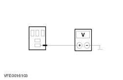
| C3: CHECK THE VOLTAGE AT FUSE F59 | |
| 1 Connect fuse F59 (CJB). | |
| 2 Measure the voltage between fuse F59 (7.5 A) and ground. | |
| Does the meter display battery voltage? Yes GO to C4. No REPAIR the voltage supply to fuse F59 using the Wiring Diagrams. CHECK the operation of the system. | |
| C4: CHECK FUSE F34 | |
| 1 CHECK fuse F34 (CJB). | |
| Is the fuse OK? Yes GO to C5. No RENEW fuse F34 (7.5 A). CHECK the operation of the system. If the fuse blows again, LOCATE and REPAIR the short using the Wiring Diagrams. | |
| C5: CHECK THE VOLTAGE AT FUSE F34 | |
| 1 Connect fuse F34 (CJB). | |
| 2 Ignition switch in position II. | |
| 3 Measure the voltage between fuse F34 (7.5 A) and ground. | |
| Does the meter display battery voltage? Yes GO to C10. No REPAIR the voltage supply to fuse F34 using the Wiring Diagrams. CHECK the operation of the system. | |
| C6: CHECK FUSE F48 | |
| 1 Ignition switch in position 0. | |
| 2 CHECK Fuse F48 (CJB). | |
| Is the fuse OK? Yes GO to C7. No INSTALL a new fuse F48 (7.5 A). CHECK the operation of the system. If the fuse blows again, LOCATE and REPAIR the short using the Wiring Diagrams. | |
| C7: CHECK THE VOLTAGE AT FUSE F48 | |
| 1 Connect Fuse F48 (CJB). | |
| 2 Measure the voltage between fuse F48 (7.5 A) and ground. | |
| Does the meter display battery voltage? Yes GO to C8. No REPAIR the voltage supply to fuse F48 using the Wiring Diagrams. CHECK the operation of the system. | |
| C8: CHECK FUSE F60 | |
| 1 CHECK Fuse F60 (CJB). | |
| Is the fuse OK? Yes GO to C9. No RENEW fuse F60 (7.5 A). CHECK the operation of the system. If the fuse blows again, LOCATE and REPAIR the short using the Wiring Diagrams. | |
| C9: CHECK THE VOLTAGE AT FUSE F60 | |
| 1 Connect Fuse F60 (CJB). | |
| 2 Ignition switch in position II. | |
| 3 Measure the voltage between fuse F60 (7.5 A) and ground. | |
| Does the meter display battery voltage? Yes GO to C10. No REPAIR the voltage supply to fuse F60 with the aid of the Wiring Diagrams. CHECK the operation of the system. | |
| C10: CHECK FUSE F26 | |
| 1 Ignition switch in position 0. | |
| 2 CHECK fuse F26 (BJB). | |
| Is the fuse OK? Yes GO to C11. No RENEW fuse F26 (10 A). CHECK the operation of the system. If the fuse blows again after switching the air conditioning on, CHECK the refrigerant compressor clutch diode and RENEW as necessary. If the refrigerant compressor clutch diode is OK, LOCATE and RECTIFY the short circuit with the aid of the Wiring Diagrams. | |
| C11: CHECK THE VOLTAGE AT FUSE F26 | |
| 1 Connect fuse F26 (BJB). | |
| 2 Measure the voltage between fuse F26 (10 A) and ground. | |
| Does the meter display battery voltage? Yes GO to C12. No REPAIR the voltage supply to fuse F26 using the Wiring Diagrams. CHECK the operation of the system. | |
| C12: CHECK THE VOLTAGE AT THE A/C CLUTCH RELAY | |
| 1 Disconnect A/C clutch relay from socket C1011 (BJB). | |
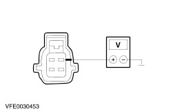
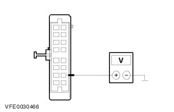
| | 2 Measure the voltage between the A/C clutch relay, socket C1011, pin 3, circuit 30-FA12 (RD), wiring harness side and ground. |
| Does the meter display battery voltage? Yes GO to C13. No LOCATE and RECTIFY the break in circuit 30-FA12 (RD) between the A/C clutch relay and fuse F26 using the Wiring Diagrams. CHECK the operation of the system. | |
| C13: CHECK THE CONTROL VOLTAGE AT THE AIR CONDITIONING CLUTCH RELAY | |
| 1 Ignition switch in position II. | |
| | 2 Measure the voltage between the air conditioning clutch relay, socket C1011, pin 1, circuit 15-FA11 (GN/YE), wiring harness side and ground. |
| Does the meter display battery voltage? Yes GO to C14. No LOCATE and RECTIFY the break in circuit 15-FA11 (GN/YE) between the A/C clutch relay and soldered connection S117 (vehicles built from 07/2006: soldered connection S54) with the aid of the Wiring Diagrams. CHECK the operation of the system. | |
| C14: CHECK THE A/C CLUTCH ELECTRICAL CIRCUIT | |
| 1 Ignition switch in position 0. | |
| | 2 Use a fused test cable (10 A) to bridge the air conditioning clutch relay, socket C1011, pin 3 and pin 5, wiring harness side. |
| 3 Check that the A/C system clutch operates correctly. | |
| Does the air conditioning clutch work? Yes GO to C17. No GO to C15. | |
| C15: CHECK THE ELECTRICAL CIRCUIT BETWEEN THE A/C CLUTCH RELAY AND THE A/C CLUTCH FOR OPEN CIRCUIT | |
| 1 Disconnect Connector C952 from the A/C clutch. | |
| | 2 Use a fused test cable (10 A) to bridge the air conditioning clutch relay, socket C1011, pin 3 and pin 5, wiring harness side. |
| | 3 Measure the voltage between A/C clutch, connector C952, pin 1, circuit 15S-FA6 (GN/YE), wiring harness side and ground. |
| Does the meter display battery voltage? Yes GO to C16. No LOCATE and REPAIR the open circuit between the air conditioning clutch relay and air conditioning clutch using the Wiring Diagrams. CHECK the operation of the system. | |
| C16: CHECK THE GROUND CONNECTION OF THE A/C CLUTCH | |
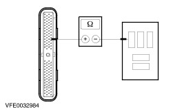
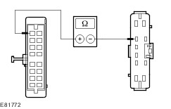
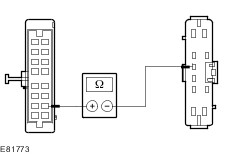
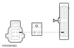
| | 1 Measure the resistance between the air conditioning clutch, connector C952, pin 2, circuit 31-FA6 (BK), wiring harness side and ground. |
| Is a resistance of less than 2 Ohm registered? Yes INSTALL A NEW air conditioning clutch. CHECK the operation of the system. No LOCATE and REPAIR the break in circuit 31-FA6 (BK) between the A/C clutch and soldered connection S109 using the Wiring Diagrams. CHECK the operation of the system. | |
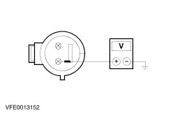
| C17: CHECK THE VOLTAGE AT THE REFRIGERANT LOW PRESSURE SWITCH | |
| 1 Disconnect connector C692 from refrigerant low-pressure switch. | |
| 2 Ignition switch in position II. | |
| 3 Switch on the blower. | |
| 4 Switch on the air-conditioning system. | |
| | 5 Measure the voltage between the refrigerant low-pressure switch, connectorr C692, pin 4, circuit 15S-FA17 (GN/OG) (vehicles built from 07/2006: circuit 91S-FA17 (BK/RD)), wiring harness side and ground. |
| Does the meter display battery voltage? Yes GO to C18. No GO to C26. | |
| C18: CHECK REFRIGERANT LOW-PRESSURE SWITCH | |
| 1 Ignition switch in position 0. | |
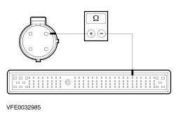
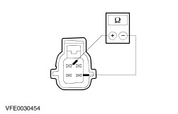
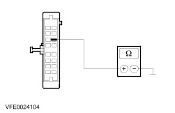
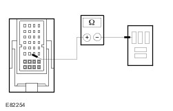
| | 2 Measure the resistance at the A/C low pressure switch, connector C692, between pin 1 and pin 4, component side. |
| Is a resistance of less than 2 Ohm registered? Yes - vehicles with 1.8L (55 KW) diesel engine and vehicles with LPG fuel system:GO to C19. - vehicles with 1.8L (66 KW) diesel engine:GO to C21. - vehicles with 85 KW engine, except vehicles with LPG fuel system:GO to C23. Vehicles built from 07/2006:GO to C37. No RENEW the refrigerant low-pressure switch. CHECK the operation of the system. | |
| C19: CHECK ELECTRICAL CIRCUIT BETWEEN A/C LOW PRESSURE SWITCH AND POWERTRAIN CONTROL MODULE (PCM) FOR OPEN CIRCUIT - VEHICLES WITH 1.8L (55 KW) DIESEL ENGINE AND VEHICLES WITH LPG FUEL SYSTEM: | |
| 1 Disconnect connector C415 from PCM. | |
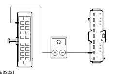
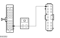
| | 2 Measure the resistance between PCM, connector C415, pin 41, circuit 15S-RE8 (GN/YE), wiring harness side and A/C low pressure switch, connector C692, pin 1, circuit 15S-RE8 (GN/YE), wiring harness side. |
| Is a resistance of less than 2 Ohm registered? Yes GO to C20. No LOCATE and REPAIR the break in circuit 15S-RE8 (GN/YE) between the A/C low pressure switch and the PCM using the Wiring Diagrams. CHECK the operation of the system. | |
| C20: CHECK ELECTRICAL CIRCUIT BETWEEN A/C CLUTCH RELAY AND PCM FOR OPEN CIRCUIT - VEHICLES WITH 1.8L (55 KW) DIESEL ENGINE AND VEHICLES WITH LPG FUEL SYSTEM | |
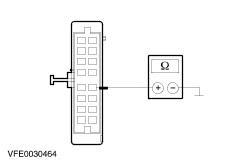
| | 1 Measure the resistance between the PCM, connector C415, pin 69, circuit 31S-FA11 (BK/YE), wiring harness side and the A/C clutch relay, socket C1011, pin 2, circuit 31S-FA11 (BK/YE), wiring harness side. |
| Is a resistance of less than 2 Ohm registered? Yes GO to C25. No LOCATE and RECTIFY the break in circuit 31S-FA11 (BK/YE) between PCM and the air conditioning clutch relay using the Wiring Diagrams. CHECK the operation of the system. | |
| C21: CHECK ELECTRICAL CIRCUIT BETWEEN A/C LOW PRESSURE SWITCH AND POWERTRAIN CONTROL MODULE (PCM) FOR OPEN CIRCUIT - VEHICLES WITH 1.8L (66 KW) DIESEL ENGINE | |
| 1 Disconnect connector C414 of PCM. | |
| | 2 Measure the resistance between PCM, connector C414, pin 19, circuit 15S-RE8 (GN/YE), wiring harness side and A/C low pressure switch, connector C692, pin 1, circuit 15S-RE8 (GN/YE), wiring harness side. |
| Is a resistance of less than 2 Ohm registered? Yes GO to C22. No LOCATE and REPAIR the break in circuit 15S-RE8 (GN/YE) between the A/C low pressure switch and the PCM using the Wiring Diagrams. CHECK the operation of the system. | |
| C22: CHECK ELECTRICAL CIRCUIT BETWEEN A/C CLUTCH RELAY AND PCM FOR OPEN CIRCUIT - VEHICLES WITH 1.8L (66 KW) DIESEL ENGINE | |
| | 1 Measure the resistance between the PCM, connector C414, pin 79, circuit 31S-FA11 (BK/YE), wiring harness side and the A/C clutch relay, socket C1011, pin 2, circuit 31S-FA11 (BK/YE), wiring harness side. |
| Is a resistance of less than 2 Ohm registered? Yes GO to C25. No LOCATE and RECTIFY the break in circuit 31S-FA11 (BK/YE) between PCM and the air conditioning clutch relay using the Wiring Diagrams. CHECK the operation of the system. | |
| C23: CHECK ELECTRICAL CIRCUIT BETWEEN A/C LOW PRESSURE SWITCH AND POWERTRAIN CONTROL MODULE (PCM) FOR OPEN CIRCUIT - VEHICLES WITH 85 KW ENGINE EXCEPT VEHICLES WITH LPG FUEL SYSTEM: | |
| 1 Disconnect connector C416 of PCM. | |
| | 2 Measure the resistance between PCM, connector C416, pin 10, circuit 15S-RE8 (GN/YE), wiring harness side and A/C low pressure switch, connector C692, pin 1, circuit 15S-RE8 (GN/YE), wiring harness side. |
| Is a resistance of less than 2 Ohm registered? Yes GO to C24. No LOCATE and REPAIR the break in circuit 15S-RE8 (GN/YE) between the A/C low pressure switch and the PCM using the Wiring Diagrams. CHECK the operation of the system. | |
| C24: CHECK ELECTRICAL CIRCUIT BETWEEN A/C CLUTCH RELAY AND PCM FOR OPEN CIRCUIT - VEHICLES WITH 85 KW ENGINE EXCEPT VEHICLES WITH LPG FUEL SYSTEM: | |
| | 1 Measure the resistance between the PCM, connector C416, pin 54, circuit 31S-FA11 (BK/YE), wiring harness side and the A/C clutch relay, socket C1011, pin 2, circuit 31S-FA11 (BK/YE), wiring harness side. |
| Is a resistance of less than 2 Ohm registered? Yes GO to C25. No LOCATE and RECTIFY the break in circuit 31S-FA11 (BK/YE) between PCM and the air conditioning clutch relay using the Wiring Diagrams. CHECK the operation of the system. | |
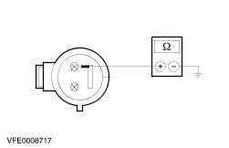
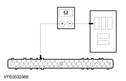
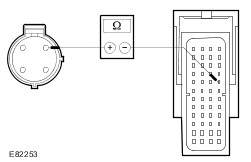
| C25: CHECK AIR CONDITIONING CLUTCH RELAY | |
| 1 Check the A/C clutch relay according to the component check at the end of the section. | |
| Is the air conditioning clutch relay OK? Yes TEST the PCM and RENEW as necessary. CHECK the operation of the system. No RENEW the air conditioning clutch relay. CHECK and if necessary RENEW the refrigerant compressor clutch diode. CHECK the operation of the system. | |
| C26: CHECK VOLTAGE AT REFRIGERANT HIGH-PRESSURE SWITCH | |
| 1 Ignition switch in position 0. | |
| 2 Disconnect connector C882 from refrigerant high-pressure switch. | |
| 3 Ignition switch in position II. | |
| 4 Switch on the blower. | |
| 5 Switch on the air-conditioning system. | |
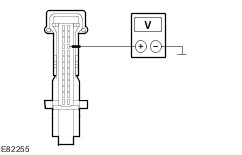
| | 6 Measure the voltage between the A/C high pressure switch, connector C882, pin 1, circuit 15S-FA38 (GN/RD), wiring harness side and ground. |
| Does the meter display battery voltage? Yes GO to C27. No Vehicles built up to 07/2006:GO to C28. Vehicles built from 07/2006:LOCATE and REPAIR the break in circuit 91-FA38 (BK/OG) between the refrigerant high-pressure switch and soldered connection S118 using the Wiring Diagrams. CHECK the operation of the system. | |
| C27: CHECK REFRIGERANT HIGH-PRESSURE SWITCH | |
| 1 Ignition switch in position 0. | |
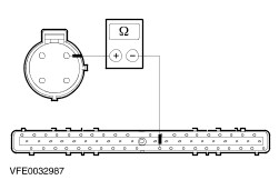
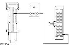
| | 2 Measure the resistance at the A/C high pressure switch, connector C882, between pin 1 and pin 4, component side. |
| Is a resistance of less than 2 Ohm registered? Yes LOCATE and RECTIFY the break in circuit 15S-FA17 (GN/OG) (vehicles built from 07/2006: circuit 91S-FA17 BK/RD)) between the refrigerant low-pressure switch and the refrigerant high-pressure switch with the aid of the Wiring Diagrams. CHECK the operation of the system. No RENEW the refrigerant high-pressure switch. CHECK the operation of the system. | |
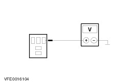
| C28: CHECK THE VOLTAGE AT THE CONTROL PANEL OF THE CLIMATE CONTROL SYSTEM - PIN 8 | |
| 1 Ignition switch in position 0. | |
| 2 Disconnect Connector C380 from the control panel for the climate control system. | |
| | 3 Measure the voltage between the control panel for the climate control system, connector C380, pin 8, circuit 29-FA13 (OG), wiring harness side and ground. |
| Does the meter display battery voltage? Yes GO to C31. No Vehicles built up to 07/2006:GO to C29. Vehicles built from 07/2006:GO to C30. | |
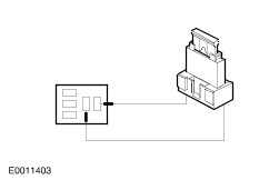
| C29: CHECK THE CIRCUIT BETWEEN THE CONTROL PANEL FOR THE CLIMATE CONTROL SYSTEM AND THE CJB FOR OPEN CIRCUIT - VEHICLES BUILT UP TO 07/2006 | |
| 1 Disconnect Connector C16 from CJB. | |
| | 2 Measure the resistance between the control panel for the climate control system, connector C380, pin 8, circuit 29-FA13 (OG), wiring harness side and the CJB, connector C16, pin 9, circuit 29-FA13 (OG), wiring harness side. |
| Is a resistance of less than 2 Ohm registered? Yes CHECK the CJB and RENEW as necessary. CHECK the operation of the system. No LOCATE and RECTIFY the break in circuit 29-FA13 (OG) between the control panel for the climate control system and the CJB using the Wiring Diagrams. CHECK the operation of the system. | |
| C30: CHECK THE CIRCUIT BETWEEN THE CONTROL PANEL FOR THE CLIMATE CONTROL SYSTEM AND THE CJB FOR OPEN CIRCUIT - VEHICLES BUILT FROM 07/2006 | |
| 1 Disconnect Connector C11 from CJB. | |
| | 2 Measure the resistance between the control panel for the climate control system, connector C380, pin 8, circuit 29-FA13 (OG), wiring harness side and the CJB, connector C11, pin 8, circuit 29-FA13 (OG), wiring harness side. |
| Is a resistance of less than 2 Ohm registered? Yes CHECK the CJB and RENEW as necessary. CHECK the operation of the system. No LOCATE and RECTIFY the break in circuit 29-FA13 (OG) between the control panel for the climate control system and the CJB using the Wiring Diagrams. CHECK the operation of the system. | |
| C31: CHECK THE VOLTAGE AT THE CONTROL PANEL OF THE CLIMATE CONTROL SYSTEM - PIN 10 | |
| 1 Ignition switch in position II. | |
| | 2 Measure the voltage between the control panel for the climate control system, connector C380, pin 10, circuit 15-FA13 (GN/RD), wiring harness side and ground. |
| Does the meter display battery voltage? Yes GO to C34. No Vehicles built up to 07/2006:GO to C32. Vehicles built from 07/2006:GO to C33. | |
| C32: CHECK THE CIRCUIT BETWEEN THE CONTROL PANEL FOR THE CLIMATE CONTROL SYSTEM AND THE CJB FOR OPEN CIRCUIT - VEHICLES BUILT UP TO 07/2006 | |
| 1 Disconnect connector C10 from CJB. | |
| | 2 Measure the resistance between the control panel for the climate control system, connector C380, pin 10, circuit 15-FA13 (GN/RD), wiring harness side and the CJB, connector C10, pin 8, circuit 15-FA13 (GN/RD), wiring harness side. |
| Is a resistance of less than 2 Ohm registered? Yes CHECK the CJB and RENEW as necessary. CHECK the operation of the system. No LOCATE and RECTIFY the break in circuit 15-FA13 (GN/RD) between the control panel for the climate control system and the CJB with the aid of the Wiring Diagrams. CHECK the operation of the system. | |
| C33: CHECK THE CIRCUIT BETWEEN THE CONTROL PANEL FOR THE CLIMATE CONTROL SYSTEM AND THE CJB FOR OPEN CIRCUIT - VEHICLES BUILT FROM 07/2006 | |
| 1 Disconnect Connector C11 from CJB. | |
| | 2 Measure the resistance between the control panel for the climate control system, connector C380, pin 10, circuit 15-FA13 (GN/RD), wiring harness side and the CJB, connector C11, pin 15, circuit 15-FA13 (GN/RD), wiring harness side. |
| Is a resistance of less than 2 Ohm registered? Yes CHECK the CJB and RENEW as necessary. CHECK the operation of the system. No LOCATE and RECTIFY the break in circuit 15-FA13 (GN/RD) between the control panel for the climate control system and the CJB with the aid of the Wiring Diagrams. CHECK the operation of the system. | |
| C34: CHECK THE GROUND CONNECTION OF THE CONTROL PANEL FOR THE CLIMATE CONTROL SYSTEM | |
| 1 Ignition switch in position 0. | |
| | 2 Measure the resistance between the control panel for the climate control system, connector C380, pin 12, circuit 91-FA13 (BK/OG), wiring harness side and ground. |
| Is a resistance of less than 2 Ohm registered? Yes GO to C35. No LOCATE and RECTIFY the open circuit in circuit 91-FA13 (BK/OG) between the control panel for the climate control system and soldered connection S12 with the aid of the Wiring Diagrams. CHECK the operation of the system. | |
| C35: CHECK GROUND CONNECTION THROUGH BLOWER SWITCH | |
| 1 Set the blower switch to position 1. | |
| | 2 Measure the resistance between the control panel for the climate control system, connector C380, pin 6, circuit 31S-FA26 (BK/RD), wiring harness side and ground. |
| Is a resistance of less than 2 Ohm registered? Yes Vehicles built up to 07/2006:GO to C36. Vehicles built from 07/2006:CHECK and if necessary RENEW the control panel for the climate control system. CHECK the operation of the system. No LOCATE and RECTIFY the break in circuit 31S-FA26 (BK/RD) between the control panel for the climate control system and the blower switch with the aid of the Wiring Diagrams. CHECK the operation of the system. | |
| C36: CHECK THE CIRCUIT BETWEEN THE CONTROL PANEL FOR THE CLIMATE CONTROL SYSTEM AND THE REFRIGERANT HIGH-PRESSURE SWITCH FOR OPEN CIRCUIT | |
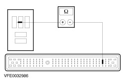
| | 1 Measure the resistance between the control panel for the climate control system, connector C380, pin 9, circuit 15S-FA38 (GN/RD), wiring harness side and the refrigerant high pressure switch, connector C882, pin 1, circuit 15S-FA38 (GN/RD), wiring harness side. |
| Is a resistance of less than 2 Ohm registered? Yes CHECK and if necessary RENEW the control panel for the climate control system. CHECK the operation of the system. No LOCATE and REPAIR the break in circuit 15S-FA38 (GN/RD) between the control panel for the climate control system and the refrigerant high pressure switch with the aid of the Wiring Diagrams. CHECK the operation of the system. | |
| C37: CHECK THE A/C REQUEST SIGNAL IN THE POWERTRAIN CONTROL MODULE (PCM) | |
| 1 Connect the diagnostic tool. | |
| 2 Switch on the blower. | |
| 3 Switch on the air-conditioning system. | |
| 4 Using the diagnostic unit, select the PCM and check in the data logger whether an A/C request signal is displayed. | |
| Is an A/C request signal displayed in the data logger of the PCM? Yes GO to C38. No GO to C40. | |
| C38: CHECK THE CIRCUIT BETWEEN THE PCM AND THE REFRIGERANT LOW PRESSURE SWITCH FOR OPEN CIRCUIT | |
| 1 Ignition switch in position 0. | |
| 2 Disconnect connector C419 from the PCM. | |
| | 3 Measure the resistance between the refrigerant low-pressure switch, connector C692, pin 1, circuit 91S-RE8 (BK/YE), wiring harness side and the PCM, connector C419, pin E4, circuit 91S-RE8 (BK/YE), wiring harness side. |
| Is a resistance of less than 2 Ohm registered? Yes GO to C39. No LOCATE and REPAIR the break in circuit 91S-RE8 (BK/YE) between the refrigerant low-pressure switch and the PCM using the Wiring Diagrams. CHECK the operation of the system. | |
| C39: CHECK FOR OPEN CIRCUIT BETWEEN AIR CONDITIONING CLUTCH RELAY AND PCM | |
| | 1 Measure the resistance between the PCM, connector C418, pin F2, circuit 31S-FA11 (BK/YE), wiring harness side and the A/C clutch relay, socket C1011, pin 2, circuit 31S-FA11 (BK/YE), wiring harness side. |
| Is a resistance of less than 2 Ohm registered? Yes GO to C25. No LOCATE and REPAIR the break in circuit 31S-FA11 (BK/YE) between the refrigerant low-pressure switch and the PCM using the Wiring Diagrams. CHECK the operation of the system. | |
| C40: CHECK THE A/C REQUEST SIGNAL IN THE CENTRAL TIMER MODULE (CTM) | |
| NOTE:The central timer module (CTM) is integrated in the instrument cluster. | |
| 1 Switch on the blower. | |
| 2 Switch on the air-conditioning system. | |
| 3 Using the diagnostic unit, select the CTM and check in the data logger whether an A/C request signal is displayed. | |
| Is an A/C request signal displayed in the data logger of the CTM? Yes CHECK and if necessary RENEW the instrument cluster. CHECK the operation of the system. No GO to C41. | |
| C41: CHECK THE CONTROL VOLTAGE AT THE INSTRUMENT CLUSTER | |
| 1 Ignition switch in position 0. | |
| 2 Disconnect Connector C809 from instrument cluster. | |
| 3 Ignition switch in position II. | |
| 4 Switch on the blower. | |
| 5 Switch on the air-conditioning system. | |
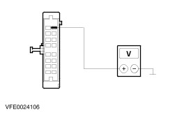
| | 6 Measure the voltage at the instrument cluster, connector C809, between pin 23, circuit 15S-FA38 (GN/RD), wiring harness side and ground. |
| Does the meter display battery voltage? Yes CHECK and if necessary RENEW the instrument cluster. CHECK the operation of the system. No GO to C42. | |
| C42: CHECK FOR OPEN CIRCUIT BETWEEN THE CONTROL PANEL FOR THE CLIMATE CONTROL SYSTEM AND THE INSTRUMENT CLUSTER | |
| 1 Ignition switch in position 0. | |
| 2 Disconnect Connector C380 from the control panel for the climate control system. | |
| | 3 Measure the resistance between the control panel for the climate control system, connector C380, pin 9, circuit 15S-FA38 (GN/RD), wiring harness side and the instrument cluster, connector C809, pin 23, circuit 15S-FA38 (GN/RD), wiring harness side. |
| Is a resistance of less than 2 Ohm registered? Yes GO to C28. No LOCATE and REPAIR the break in circuit 15S-FA38 (GN/RD) between the control panel for the climate control system and the instrument cluster with the aid of the Wiring Diagrams. CHECK the operation of the system. | |
Source: https://workshop-manuals.com/ford/transit.tourneo_connect_2002.5_06.2002/mechanical_repairs/4_electrical/412_climate_control_system/412-00_climate_control_system_general_information/diagnosis_and_testing/climate_control_system/
Posted by: janetabatces0.blogspot.com

Posting Komentar